Gas Springs Design
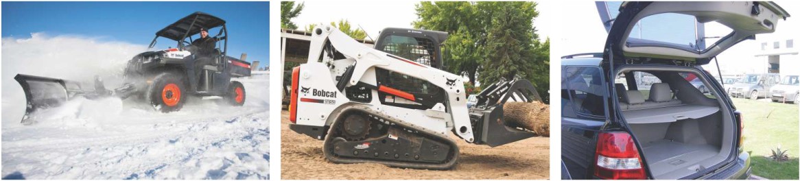
Gas springs are used to lift or counter balance an object but are also used to resist or decelerate a moving object. They are used extensively on automobiles to lift hoods, trunks, lift gates, etc. along with trucks, buses, farm equipment to name a few.
Gas springs are often used to replace mechanical springs because they offer several major advantages:
- Gas springs provide force at their extended length position; mechanical springs provide zero force in their free length position and need to be compressed to a pre-load position often making assembly difficult.
- Gas springs can achieve very low spring rates and require half the packaging space of mechanical springs.
- Gas springs can extend at a velocity designed for the application, something that a mechanical gas spring cannot do.
- Using groove tube technology the shaft velocity can have multiple extension rates throughout its travel. The biggest use of this technology is to decelerate an object towards the end of travel and have the object come to acontrolledstop.
- You can also dampen standard gas springs by increasing the amount of oil in the tube but there are requirements of the application angle to make this work.
How is this all possible? Gas springs are energy storage devices as are mechanical springs. Mechanical springs store energy as the material is strained during operation, a gas spring provides force via compressed gas. This force increases as the shaft is pushed inside the tube compressing the gas further and storing more energy. We have identified the Advantages of gas springs but there are also a couple of disadvantages that have to be over come.
- Temperature – As the temperature changes the pressure inside the gas spring also changes. At low temperatures the pressure drops and at high temperatures the pressure increases. When specifying the force output of the spring this should be taken into account.
- Force Loss – Gas springs will lose pressure over time, in general 1 % – 2% per year, the actual amount is dependent on the spring design. The loss is due to gas molecules permeating through the rubber seal, the more gas you have inside the gas spring the lower the effect on force.
In general you should design the spring at the lowest temperature it will be required to work in and add 2% additional force for every year the product is designed to function.
With this additional force you need to check the gas spring at its highest working temperature to ensure it does not provide too much force for the design to function correctly.
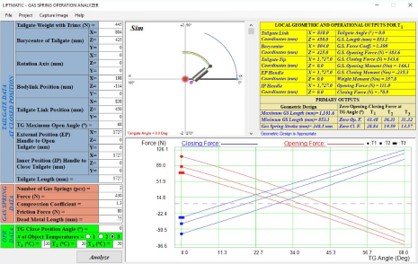
Analysis
LiftMatic can run a simulation of the design at 3 different temperatures to understand how the system will function in hot and cold conditions.
We can provide the force required to open and close, at what angle the lid will self-rise and if it will hold open at the desired angle. Running this analysis during the initial design stage can save a lot of headaches down the road.
LiftMatic requires basic information about the system, Weight, center of gravity, attachment points, operating angle and handle location. With this we can run simulations of the system and identify the optimummounting locations
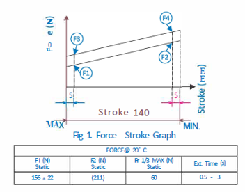
Force Measurement
The load cell is set to zero and the parts are then compressed at a speed of 200/min then held at a static point, 5mm into the stroke (P3 or F3), and 5mm before the end of stroke, (P4 or F4) for 5 seconds, then the test resumes. On the return or extension stroke the process repeats, but in reverse order (P2 or F2) then P1 or F1 Dynamic Fr: This refers to the amount of friction between the seals and the shaft while the shaft is motion, taken at the midpoint (FC), on both the compression and extensionstroke, withoutstopping.
Static Fr: This refers to the amount of friction between the seals and the shaft while the shaft is at a static position, taken 5mm into the compression stroke (P3 or F3) and 5mm from full extension (P1 or F1 ).
Dynamic FC: This is the comparison of the amount of force being applied by the gas spring itself, at the mid point (FC), while it is being compressed and then allowed to extend in motion and not static.
Sample rate is 500hz or 500 data points per second.